

An innovative concept in the weaving of 3D seamless complex woven preforms
A limitation of 2D carbon fibre reinforcement is that, when moulds are used, problems, such as wrinkling, occur in complex shapes.
Carbon fibre-reinforced plastics (CFRPs) have a high strength and stiffness-to-weight ratio; therefore, these materials can substitute, for example, metals, and they are widely used in various industries such as the automobile and aerospace industries. Because two-dimensional (2D) fibre-reinforced plastics (FRP) have no reinforcing elements in the thickness direction, mechanical properties deteriorate in that direction. Delamination of 2D FRPs is one of the main causes of their poor mechanical properties. Various methods, including z-pinning, stitching, tufting, resin toughening, and interface strengthening, have been employed to solve this problem; however, no complete solution has been provided. To overcome the limitations of 2D FRPs, several studies have been conducted on novel 3D preform weaving methods. The three most representative three-dimensional (3D) woven structures are the orthogonal (ORT) structure, layer-to-layer (LTL) structure, and angle-interlock (AI) structure. Numerous studies have been carried out to evaluate and characterise the mechanical properties for these three structures. In addition to these established weaving structures, research has been undertaken to explore new weaving techniques. An examination of flexural behaviour was conducted through the design of a novel weaving technology, utilising a modified heddle position system based on a self-built 3D loom, resulting in the production of four representative 3D weaving structures. Subsequently, an experimental investigation was carried out to assess the low-velocity impact performance of six types of 3D woven structures. Furthermore, studies have been dedicated to the development and multiscale characterisation of 3D warp interlocked flax fabrics with different weave structures for composite applications. Research efforts have also focused on enhancing delamination resistance and out-of-plane mechanical properties through 3D fully interlaced preform weaving. Additionally, new 3D woven ORT fabrics with improved auxeticity are currently under development for reinforced composites. Various woven structures have been proposed, designed, and manufactured. The overall strength, delamination resistance, and impact performance of the 3D woven composites were found to be excellent owing to the effect of the thick reinforcing yarn (z-binder).
CFRPs used in industries such as automobiles and aerospace must have a specific structural shape depending on the usage. Presently, 2D carbon fibre reinforcements in the form of fabrics are laminated for this purpose and then placed into a mould of a specific structure to make a composite material. A limitation of these technologies is that, when moulds are used, problems, such as wrinkling, occur in complex shapes. Alternatively, after these reinforcing materials assume the shape of a structure, joints are added to create a shape. In the case of creating a joint, even if the problem of complexity is solved, there are weaknesses in the joint, such as a considerably long manufacturing time and difficulty in injecting resin.
Therefore, 3D woven preforms offer the best solution for high-performance applications with complex geometries. These preforms are specially woven to fit the desired shape. It also exhibits a uniform and well-aligned fibre distribution. Previous studies have reported on seamless 3D composite manufacturing technology, but only for manufacturing of fragmented specimen. Owing to the complexity of the manufacturing technology, reports on mass production technology are also lacking. Textile reinforcement forming held an advantage in terms of its process simplicity and speed. However, it suffered from drawbacks such as wrinkling, buckling, and network sliding. Surface 3D weaving excelled in producing intricate structures with fewer defects but faced limitations for fibre plies with specific orientations, and its weaving process was time-consuming. The mathematical determination of shapes of reed wires demonstrated an advantage in creating seamless and specific shapes, but it was constrained in the variety of shapes it could produce and required numerous corrections, rendering it time-intensive. Paper-folding approaches offered the benefit of seamlessness, yet they had restrictions on the shapes achievable, resulting in uneven tension and irregular surfaces. Research has been conducted to facilitate the use of these 3D composite materials as parts; however, the complexity of the manufacturing process has not been resolved. Therefore, the development of simple, continuous, and rapid seamless 3D composite manufacturing technology has great academic and industrial significance.
In this study, the equipment for 3D woven preform manufacturing has been introduced, and the weaving mechanism has been discussed. We present three representative 3D weaving structures: through-thickness orthogonal structure (TTO), through-thickness layer-to-layer structure (TTLL), and through-thickness all-layer-interlaced structure (TTAL). These differ according to the degree of z-binder interlacing using a novel weaving mechanism. The effect of the z-binder interlacing on the structure was also analysed. Based on the 3D woven weaving mechanism, a manufacturing process for seamless 3D complex woven preforms was established. Our weaving method, exemplified by the TTAL structure, possesses a distinct advantage in that it enables the weaving of diverse structures through careful structural design. This approach allows for the realisation of complex shapes. Through the concept of weft and warp slices, convex and concave shapes with non-uniform heights in the z-direction were produced. This was possible because of the continuity and diversity of the TTAL structure. Furthermore, box, box lid, bowl, pyramid, and bowl-type preforms with increased complexity were produced; post-manufacturing, the internal structure was analysed to confirm continuity. Consequently, we advocate for our method as a ‘new weaving technology’ with significant potential for the effective, continuous, efficient, and rapid manufacturing of various 3D woven structures.
3D weaving loom and basic weaving mechanism
Figure 1 shows a schematic representation of the 3D weaving equipment developed in this study. Figure 1 (a) shows an overview of the 3D weaving equipment with key elements. The key elements include torque motors, heddle frames, reed, warp yarns, z-binder yarns, and weft yarns. Torque motors are used to supply warp and z-binder yarns. To ensure that all fibre yarns remain straightened during the weaving process, a torque motor provides a constant tension. The weft yarns are inserted at the corresponding positions according to the upward and downward movements of the heddle frame. Therefore, to insert the weft yarns at the desired position, the up and down movements of the heddle frame have to be set correctly. After the weft is inserted, a compact 3D woven structure is formed after the beating-up process of the reed. Figure 1 (b) shows the xz-plane view of the 3D weaving equipment in three parts: supplying, weaving, and taking-up. In the supplying part, the warp and z-binder yarns are only unwound to the length necessary for the next step of the weaving process. In the weaving part, the warp and z-binder yarns are arranged at the required positions to create the desired 3D structure. In this part, we determine whether the warp and z-binder yarns are situated above or below the weft yarn in the z-direction. The wefts are inserted between the warp and z-binder yarns, which are opened up and down using a heddle frame. The final 3D structure are determined by the relative positions of the warp, weft, and z-binder yarns along the z-direction. Finally, the preform is pulled in the x-direction in the take-up part, and the fibre volume fraction can be controlled through an appropriate pitch shift. Figure 1 (c) shows a built-in machine in a laboratory with key elements: torque motors, heddle frames, and reed.
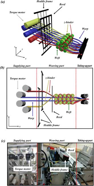
Figure 1: Schematic representation of the new 3D weaving equipment: (a) overview, (b) individual parts in the xz-plane view, and (c) built-in machine in a laboratory.
The 3D weaving process takes place in eight steps and explains the mechanism of the 3D weaving equipment. Prior to weaving, both heddle frames of the warp yarns and z-binder yarns are in a lowered state without any positional distinction. As weaving commences, the position of the weft yarns along the z-axis is determined by the up-and-down movement of the heddle frame. The process of inserting the first weft yarn into the top layer. The weft yarn is inserted in the space between the raised yellow z-binder heddle and the lowered red z-binder heddle, known as the weaving point. This weaving point is consistent in all the weaving processes and is marked by the intersection of the red dotted line. The insertion of the weft yarn with only the red z-binder heddle raised. The two z-binder heddles are alternately raised during the weaving process, causing the z-binder yarns to interlace with the inserted weft yarns. The insertion of the weft yarn happens into the middle layer. Because the weaving point remains the same, one of the two warp heddles must be raised. The insertion of the weft yarn goes into the bottom layer. At this stage, both warp heddles are lifted. Subsequently, one weft yarn is inserted into the bottom layer and another weft yarn is inserted into the middle layer show one cycle in which six weft yarns are inserted. The dense structure is produced by beating-up after each weft yarn is inserted.
Yarn to yarn friction is well known as the main influence on the degradation of carbon yarns. In our study, yarn degradation caused by friction was managed by preventing unnecessary contact between yarns, maintaining appropriate tension, setting the appropriate pitch shifting, controlling the temperature and humidity in the laboratory, and reducing unnecessary stress by minimising process variables.
Materials and 3D composites fabrication
Carbon fibre yarns (A-38, A-42, DOWAKSA, Turkey) were used, and the tensile strength of each carbon fibre yarn was 3800 MPa and 4200 MPa. Three different 3D woven structures (TTO, TTLL, and TTAL) were fabricated using warp, weft, and z-binder yarns of 6K (A-38), 12K (A-42), and 3K (A-38) carbon fibres, respectively. For the example fabrication of the seamless 3D woven preforms with complex shapes, 24K (A-42) carbon fibres were used for the warp, weft, and z-binder yarns.
The matrix consisted of epoxy resin and a hardener (Epofix; Struer, USA). The epoxy resin and hardener were mixed in a weight ratio of 25:3 at room temperature. Vacuum-assisted resin transfer moulding was used to impregnate the 3D woven preforms with the epoxy resin system. After defoaming, the mixed resin was injected into a vacuum bag, and the composite was cured for 24 h at room temperature in a sealed bag.
Characterisation of 3D woven composites
To analyse the fibre architecture of the 3D woven composites, micro-CT imaging (Skyscan 1275; Bruker, Belgium) was used. Datasets were reconstructed using standardised cone-beam reconstruction software (NRecon; Bruker, Belgium). For 3D visualisation of the 3D woven composite, a volume rendering software (CTVox; Bruker, Belgium) was used. Through structural rendering using an analysis and visualisation software (CTAn; Bruker, Belgium), the fiber volume fraction and porosity of the composite were measured.
The specimens for tensile testing were prepared according to the ASTM D3039 standard (100 × 15 × 2 mm³). End tabs, each with a length of 20 mm, were attached to both ends of the specimen using an epoxy adhesive (DP460; 3 M, USA), making a gauge length of 600 mm. Tensile testing was performed using an Instron 5985 instrument (Instron, USA) at a loading speed of 2 mm/min with a 100 kN load cell. Bending testing was also performed with the specimens prepared according to ASTM D790 (55 × 12.7 × 2 mm). A universal tensile tester (Quasar 50, Galdabini, Italy) equipped with a three-point loading system was used for bending tests. The crosshead speed was 1.0 mm/min, and the sample span-to-depth ratio was 16:1. A minimum of five specimens were tested.
Fabrication of 3D woven preforms and composites
Various 3D woven structures by different z-binder interlacing: To investigate the effect of different z-binder interlacings on the 3D woven structures, we fabricated three representative 3D woven preforms in a three-layer through-thickness structure. All the three structures contained six wefts in a repeat cycle. The TTO structure contains z-binder yarns that wrap around three weft yarns covering the entire z-direction. The TTLL structure has z-binder yarns that wrap around one weft yarn and then two weft yarns, whereas the TTAL structure has z-binder yarns that wrap each weft yarn, i.e., wrap three times, one at a time. These weaving structures were fabricated by adjusting the weaving process. To clarify explain this and in fact monitor the weaving process, a weaving process diagram is devised. In the weaving process diagrams, the z-binder and warp heddles are represented by “B” and “W†and the numbers behind these denote different heddles that are used to achieve the desired weaving pattern. Note that the colours in the diagram match the colours of warp, weft, and z-binder yarns in the 3D woven structures. The lifting and lowering of a specific heddle are indicated by the filled and blank sections of the diagram, respectively. The first weaving steps for all the three structures were identical. The initial weft was inserted and woven below the raised B1, W1, and W2 heddles and above the descended B2 heddle. The second weft for the TTO structure was woven below the raised B1 and W1 heddles and above the descended B2 and W2 heddles. In contrast, the second wefts of the TTLL and TTAL structures were woven below the raised B2 and W1 heddles and above the descended B1 and W2 heddles. For the third weft, the B1 heddle was raised in the TTO and TTAL structure, whereas the B2 heddle was raised in the TTLL structure. Although W1 and W2 were the same configuration for all three structures, different motions of B1 and B2 heddles wrapped wefts by the z-binders simultaneously, fabricating the desired pattern and structure.
3D geometrical solid models of the three representative 3D woven structures discussed above and real CT images of their fabricated 3D woven composites manufactured using proposed weaving mechanism. After cutting the samples into dimensions of x = 30 mm and y = 5 mm, micro-CT scanning, reconstruction, and volume rendering were performed sequentially. The micro-CT results were in agreement with the designed structures, indicating that the weaving process was successful. Upon closer examination of each structure, the TTO structure exhibited densely arranged wefts in the z-direction because of the z-binders surrounding the three wefts. Conversely, in the TTAL structure, the z-binders were wrapped around each weft, resulting in regularly spaced wefts, the TTLL structure was an intermediate form between the TTO and TTAL structures, i.e., the z-binder wrapped one and two wefts in subsequent cycle. As such, the weft yarns were not evenly arranged and were slightly twisted.
Effect of z-binder interlacing on directional fibre volume fraction: The three structures (TTO, TTLL, and TTAL) exhibit different z-binder waviness and patterns, which significantly influence the textile architecture of 3D woven composites. The specification of textile architecture of the fabricated 3D woven composites have been determined. The warp, weft, and z-binder fibres had counts of 6K, 12K, and 3K, respectively. The numbers of yarns per unit length for the warp, weft, and z-binder are listed in the table as ends/cm, picks/cm, and binders/cm, respectively. The areal density of the dry 3D woven preform, measured in g/m2, and the thickness of the 3D woven composite (measured in mm) are also provided in the table. Because of the large curvature of the z-binder yarn of TTAL structure, which interlaces all wefts, a thinner yarn than the warp or weft was selected for the z-binder. The z-binder architecture significantly affects void content, directional fibre volume fraction, mechanical properties, failure mechanisms, and other factors. All the warp densities were the same, whereas the weft density and thickness varied depending on the z-binder architecture. The weft and z-binder densities vary due to these structural differences. Notably, the warp density for all these structures remains constant at 4 ends/cm. However, the weft density increases progressively from 6, 6.92 to 7.66 picks/cm, respectively. Initially, the z-binder density is uniform at 4 binders/cm across all structures, but it subsequently increases to 5.37, 9.82, and 14.24 binders/cm, respectively, based on the specific structure. Consequently, the area density increases from TTO to TTAL. In the micro-CT image obtained, the weft yarn in the TTO structure is a long oval shape in the x-direction. Conversely, in the TTAL structure, the weft yarn closely approaches a circular shape due to the wrapping of all weft yarns by the z-binder. This z-binder influence leads to an increase in the thickness of the structure, particularly in the case of the TTAL structure.
The fibre, matrix, and void volume fractions of the 3D woven composites. The TTAL structure exhibited the highest fibre volume fraction (53.33 per cent), which is attributed to its high z-binder content. However, it also had the highest void content of 2.28 per cent because the z-binders induced more voids in the 3D woven composites than in the 2D composites. The z-binders reduced the resin flow between the warp and weft yarns, thereby decreasing the amount of resin in the area. The TTLL structure had a smoother (i.e., small curvature of z-binder yarn) weaving pattern than the TTAL structure, whereas the TTO structure had the smoothest pattern. A smoother weaving pattern results in a better resin flow between the woven layers and resin infiltration into the woven fabric , which leads to a lower void content. Thus, the TTO structure had the lowest void content, and the TTAL structure had the highest void content with the most complex weaving pattern.
The directional fibre volume fractions, which were obtained by the total fibre volume fraction with the warp, weft, and z-binder contents, have been determined. From TTO to TTAL structures, the wrapping region of the z-binder yarns around the weft yarns was increased. This alteration created more space between the warp layers in the composites, leading to larger dimension in the xz-plane. Despite having the same number of warp yarns, the increased dimensions resulted in a reduced fibre volume fraction. As a result, the TTAL structures exhibited the lowest fibre volume fraction in the warp direction. Conversely, the expansion of the wrapping region of the z-binder yarn led to a higher fibre volume fraction in the z-binder direction. This is evident from the TTAL structure, which showed the highest fibre volume fraction in the direction. It is important to note that while the majority of z-binder yarns in the TTO structure were aligned with the thickness direction, in the other two cases, some sections of the z-binder yarns were not aligned. Taking into account the influence of the z-binder on the x- and z-directions, we calculated the fibre volume fraction in the x-, y-, and z-directions. The values have been determined. The TTAL structure exhibited higher x- and z-direction fibre volume fractions compared to the other two structures, owing to the high z-binder fibre volume fraction. Considering the overall thin structure and the significant curvature of the z-binder in the TTAL structure, the fibre volume fraction in the z-direction was relatively low. However, this can be further increased by adjusting the structure’s thickness and a different type of yarn, making it possible to fabricate full 3D woven preform. Subsequently, the mechanical properties of the three 3D woven composites were investigated as follows.
References
- Golra, O.A., et al., Strategy for introducing 3D fibre reinforced composites weaving technology. Procedia Technology, 2012. 1: p. 211-216. 18.
- Liu, Y., et al., Research on development of 3D woven textile-reinforced composites and their flexural behaviour. Materials & Design, 2021. 212: p. 110267. 19. Hu, Q., et al., A comprehensive study on the mechanical properties of different 3D woven carbon fibre-epoxy composites. Materials, 2020. 13(12): p. 2765.
- Huang, T., Y. Wang, and G. Wang, Review of the mechanical properties of a 3D woven composite and its applications. Polymer-Plastics Technology and Engineering, 2018. 57(8): p. 740-756. 24.
- Liu, Y., H. Xia, and Q.-Q. Ni, Experimental investigation on low-velocity impact performance of 3D woven textile composites. Applied Composite Materials, 2022. 29(1): p. 121-146. 25.
- Lansiaux, H., et al., Development and Multiscale Characterisation of 3D Warp Interlock Flax Fabrics with Different Woven Architectures for Composite Applications. Fibres, 2020. 8(2): p. 15. 26.
- Perera, Y.S., et al., Evolution of 3D weaving and 3D woven fabric structures. Fashion and Textiles, 2021. 8(1): p. 1-31. 27.
- Weerasinghe, S., et al. Method and apparatus to weave a fully interlaced three-dimensional textile structure. in 2017 Moratuwa Engineering Research Conference (MERCon). 2017. IEEE. 28.
- Khan, M.I., et al., Development of composites, reinforced by novel 3D woven orthogonal fabrics with enhanced auxeticity. Journal of Industrial Textiles, 2019. 49(5): p. 676-690. 29.
- N.Gokarneshan and U.Ratna, A review of some innovative concepts in the weaving of technical fabrics, SSRG International Journal of Polymer and Textile Engineering Volume 8 Issue 2, 9-12, May-Aug 2021.
- N.Gokarneshan et.al, Recent innovations in jacquard weaving technology, Journal of Textile Engineering and Fashion Technology, Volume 1, Issue 1, 2019.
About the authors:
Dr N Gokarneshan is from the Department of Textile Chemistry, SSM College of Engineering, Komarapalayam.
Dr D Anita Rachel is from the Fashion Design Department, Footwear Design and Development Institute, Noida.
Hari Priya is from the Department of Costume Design, Dr SNS Rajalakshmi College of Arts and Science, Coimbatore.